Citrix XenServer 6.0 Installing XenServer and XenCenter


Citrix XenServer 6.0 Installing XenServer and XenCenter


XenServer Requirements


XenServer runs directly on your hardware, so there won't be anything between your hardware and XenServer. In other words, XenServer will function literally as the operating system. It will talk directly to your hardware, including your network interface card (NIC) and storage controller.

It requires a 64-bit CPU with Intel VT or AMD-V enabled. Now, this is actually more like a recommended spec. It doesn't mean that XenServer won't install if your CPU isn't Intel VT or AMD-V enabled, it will. However, the features and functionality will be very limited.

Remember, XenServer is a paravirtualized hypervisor. It uses the paravirtualization technique of server virtualization. Therefore, it requires the processor that you have on your physical server to be capable of doing virtualization technology in order for you to leverage its capabilities.

You need a minimum of 2 GB of RAM just to install XenServer, but the recommended is at least 8 GB, especially if you intend to host multiple virtual machines on top of it. XenServer alone will require 16 GB of disk space. But again, you'll need more for your virtual machines.
It can work with a 100 Mb NIC controller. However, what is really recommended is a Gigabit or even a 10 Gigabit Ethernet controller.


XenServer Hardware Capabilities


You can put up to 1 TB of RAM, 16 NICs, and 64 logical processors on one physical host running XenServer. Remember that the logical processors is a combination of the cores, the hyperthreading that’s enabled, etc.

I strongly recommend you check the hardware compatibility list (HCL) at hcl.xensource.com before you purchase any of the hardware or peripherals you intend to attach to your server.

In most cases, when you go to a software vendor and tell them what you’re going to use the server for (e.g. for XenServer), they’ll first check for compatibility. However, since you may tend to buy peripherals like HBAs, NICs, and other items for the server, you want to make sure that those items are also included in the HCL to avoid issues during installation or even after.

XenServer was actually meant to be installed on server class hardware. However, because it’s a Linux distribution and because it’s using the paravirtualization technique of virtualizing, it tends to be compatible with a wide range of desktops or even laptops.
So if you want to experiment, you can actually install XenServer on a laptop or on a workstation. Odds are, it will work.

Actually, XenClient, which is the Citrix’s Type 1 Client Hypervisor (XenServer is primarily for servers class computers, while XenClient is primarily for clients such as laptops and desktops), is built off of the same hypervisor as XenServer. That is why you can get away with installing XenServer on workstation class hardware.


Downloading Citrix XenServer 6 and XenCenter

You can download XenServer and XenCenter from www.citrix.com/xenserver. Or if you have a MyCitrix account, you can go to www.citrix.com/mycitrix and download it from there.

XenServer 6 is a 508 MB (ISO) download, while XenCenter is a 41 MB download.

10 minutes to Xen

Setting up XenServer is fast and easy. Here are the steps:

Burn the downloaded ISO to a CD and insert it into your optical drive or mount it using software like MagicISO.

Make sure VT (or AMD-V) is enabled in your server’s BIOS.

Boot to the CD.

Answer the basic installation questions and reboot.

Perform initial configurations, such as assigning it an IP address, a host name, password, and so on.

Connect to your XenServer using XenCenter.

That entire process should take you only right about 10 minutes and I’m going to walk you through that in a few moments.


XenCenter Installation Requirements

Citrix XenCenter is a Windows-based application which can be installed on either a physical or virtual machine.

   
It should be installed on any of the following Windows flavors: Windows XP, Vista, 7, Server 2003, 2008, and 2008R2. It requires .NET Framework 3.5.

Its minimum CPU requirement is 750 MHz but 1 GHz is recommended. Minimum required RAM is 1 GB but the recommended is 2 GB. It occupies 100 MB of disk space and operates on a NIC with at least 100 Mb speed. Finally, the minimum required screen resolution is 1024 x 768.


Now that we’re done with that, let’s jump into the installation process.

Installing XenServer

Mount the ISO CD on your physical server.


Once it boots up, it’s going to start installing automatically. 


The first thing it will want to know is the type of keyboard you intend to use. Choose one and click OK.

Click OK again.

Feel free to read the License Agreement and then click Accept EULA once you’re done.

My CPU is already enabled with Intel VT. However, I chose to disable it in order to show you what you’ll encounter when installing XenServer on a system that doesn’t have Intel VT (or AMD-V) enabled. So, if your system has Intel VT (or AMD-V) but you’ve forgotten to enable it, this is what you’ll see. 

All you have to do is go back into your BIOS and enable it there. For now, let’s just see what happens when you click OK.
Apparently, the system will proceed to ask you where you would like to install XenServer. In my case, I have 50 GB of local disk space free, so I’m going to go ahead and install my XenServer there. I just select that and click OK.

Select the source of your installation media. In my case, it’s Local media, but it can be HTTP, FTP, or NFS for you. Click OK.

You’ll then be asked whether you wish to install any supplemental packs like drivers of anything of that sort. In my case, I don’t have any so I just select No.

After that, you’ll be asked whether you want to verify the integrity of the ISO you downloaded to make sure it’s not corrupted and that it’s a good ISO to install from. Since I’m sure my ISO’s good, I’ll just opt to skip this part and click OK.

Set a password for your root account and click OK.

You can then choose whether to allow DHCP to assign this installation an IP address or to assign an IP address yourself. In my case, I’ll just let DHCP do the assigning.

Next up will be the Hostname Configuration. Again, you can either let DHCP take care of that for you or you can assign a hostname yourself. I’ve chosen to assign one myself, giving it the name “xs.trainsignal.com”. However, I’ll leave it to DHCP to set the DNS Configuration. As you can see, you may also do things manually. Click OK.

Find your geographical location, select it, and click OK.

Find the city or area you’re in, select it, and click OK.

If you have an NTP server, it is critical that you configure the time settings on your XenServer properly. And really, if you’ll be doing multiple installations of XenServer, you should have an NTP server of some sort running on your network. Once that’s ready, you can select Using NTP on this screen and then enter your NTP server’s IP address on the succeeding screen.
But for this walk through, I’m just going to go ahead and select the Manual time entry option.

Click OK.

At this point, you should be ready to install XenServer, so go ahead and click Install XenServer.

Next you'll see the Preparing for Installation screen.

If you chose to set the time manually like we did, you’ll see something like this:

Enter the correct time (or see to it that everything’s alright) and then click OK.
When you get to the Installation Complete screen, click OK to complete the process.

You’ll then go through one final reboot, immediately after which your XenServer should be up and ready to go. Just be sure to eject the optical media that contained your installer.

What you’ve gone through so far covered the basic configuration of your server. It already included an IP address assignment, so you can connect to that server immediately after. Take note of that IP address because you’re going to need that in a short while.

Installing XenCenter
So now let me take you through the installation process for XenCenter where I can show you how to connect it to your newly configured server.
Download the installation file for XenCenter to a remote Windows environment. 

Once it’s ready, launch the installer. It’s just a simple installation, so basically you just need to keep on clicking Next until you get to the screen with the Install button. Click that.

Click Yes.

And then click Finish.

Tour of XenCenter
Before we wrap things up, let me give you a brief tour of XenCenter. Launch the program from the Start menu.

The first thing it’s going to ask you is whether you want it to periodically check the Internet for updates. I suggest you click Yes.

Here’s how XenCenter looks like (see screenshot below) before any hosts, resource pools, and so on, are added to it.
To connect to the XenServer host you configured earlier, click Add a server.

Enter the IP address I asked you to take note of earlier. Also enter the password you assigned for your root account. Click Add.

One of the first things you want to make sure as you’re adding a new XenServer to XenCenter is to save and restore the server connection state on startup. Check the box that will do just that.

Once you do that, you will be allowed to configure a master password for all the XenServers you’ll be associating with this XenCenter. Click the Require a master password checkbox if that’s what you want to do, and then enter your desired master password in the fields provided.

After you click OK, you’ll be brought back to the main screen, where you’ll see your XenServer already added to XenCenter. 


Windows Server 2003 Booting Process

Boot sequence for Windows NT, 2000, XP and 2003:

BIOS: performs Power On Self Test (POST)
BIOS: loads MBR from the boot device specified/selected by the BIOS

MBR: contains a small amount of code that reads the partition table, the first partition marked as active is determined to be the system volume 


MBR: loads the boot sector from the system volume

BOOT SECTOR: reads the root directory of the system volume at loads NTLDR

NTLDR: reads BOOT.INI from the system volume to determine the boot drive (presenting a menu if more than 1 entry is defined)
NTLDR: loads and executes NTDETECT.COM from the system volume to perform BIOS hardware detection
NTLDR: loads NTOSKRNL.EXE, HAL.DLL, BOOTVID.DLL (and KDCOM.DLL for XP upwards) from the boot (Windows) volume
NTLDR: loads \WINDOWS\SYSTEM32\CONFIG\SYSTEM which becomes the system hive HKEY_LOCAL_MACHINE\System
NTLDR: loads drivers flagged as "boot" defined in the system hive, then passes control to NTOSKRNL.EXE

NTOSKRNL.EXE: brings up the loading splash screen and initializes the kernel subsystem
NTOSKRNL.EXE: starts the boot-start drivers and then loads & starts the system-start drivers
NTOSKRNL.EXE: creates the Session Manager process (SMSS.EXE)

SMSS.EXE: runs any programs specified in BootExecute (e.g. AUTOCHK, the native API version of CHKDSK)
SMSS.EXE: processes any delayed move/rename operations from hotfixes/service packs replacing in-use system files
SMSS.EXE: initializes the paging file(s) and the remaining registry hives
** before this step completes, bugchecks will not result in a memory dump as we need a working page file on the boot (Windows) volume **
SMSS.EXE: starts the kernel-mode portion of the Win32 subsystem (WIN32K.SYS)
SMSS.EXE: starts the user-mode portion of the Win32 subsystem (CSRSS.EXE)
SMSS.EXE: starts WINLOGON.EXE

WINLOGON.EXE: starts the Local Security Authority (LSASS.EXE)
WINLOGON.EXE: loads the Graphical User Identification and Authentication DLL (MSGINA.DLL by default)
WINLOGON.EXE: displays the logon window
WINLOGON.EXE: starts the services controller (SERVICES.EXE)
** at this point users can logon **

SERVICES.EXE: starts all services markes as automatic

---------

NOTES:
The SYSTEM volume is the partition from which the boot process starts, containing the MBR, boot sector, NTLDR, NTDETECT.COM & BOOT.INI

The BOOT volume is the partition which contains the Windows folder - this can be a logical partition


Physical and Logical Structure of Active Directory

In comparison to the logical structure, which performs administrative tasks, the Active Directory physical structure checks when and where logon and replication traffic occurs. The physical structure of Active Directory contains all the physical subnets present in your network like domain controllers and replication between domain controllers.
The physical structure of Active Directory:
             Domain Controllers: These computers run Microsoft Windows Server 2003/2000, and Active Directory. Every Domain Controller performs specific functions like replication, storage and authentication. It can support maximum one domain. It is always advised to have more than one domain controller in each domain.
             Active Directory Sites: These sites are collection of well-connected computers. The reason why we create site is domain controllers can communicate frequently within the site. This way it minimizes the latency within site say changes made on one domain controller to be replicated to other domain controllers. The other reason behind creating a site is to optimize bandwidth between domain controllers which are located in different locations.
All IP subnets who share the common Local Area Network (LAN) connectivity without knowing the actual physical location of computers is called site.
Let's take an example: A site has subnets 192.168.5. A and 192.168.50.A, where 192.168.5.A computer is located in Texas and 192.168.50.A computer is located in London. In this case physical location of both the computer is not known to user. Because of proper bandwidth between these two, they are able to work and configure computers within the same Active Directory Site.
Few considerations an Administrator should examine before creating a new site are proper bandwidth, available bandwidth cost and replication traffic expected.
             Active Directory Partitions: Each Domain Controller contains the following active directory partitions:
o             The Domain Partition contains a copy of all the objects in that domain. Replication in Domain Partition is only to other domain controllers which are in the same domain.
o             The Schema Partition is forest wide. Every forest has one schema with consistent object class. The Schema and Configuration take part in replication, and get replicated to all domain controllers in a forest.
o             Application Partition which is optional carries objects which are not related to security and can be used by one or more applications. Application Partition replicates to specific domain controller in the forest.
Logical Structure of an Active Directory
Active Directory fulfills all the needs of an organization by designing a directory structure. It provides flexibility in designing the business structure according to current and future needs for an organization, so it should be examined prior to installing active directory. In Active Directory, resources are organized in a logical structure, and this grouping of resources logically enables a resource to be found by its name rather than by its physical location.
Benefits of AD Logical Structure
             Logical Structure provides more network security by means of providing access to resources to only specified groups (OU).
             Logical structure simplified the network management by administration, configuration and control of the network.
             The relationship between the logical structure of domains and forests simplifies resource sharing across an organization.
             As logical structure provides simplified network management, it reduces the load on network resources and lower the total cost of ownership.
Components of AD Logical Structure
The logical structure components have relationship with each other so it manage to control access to stored data and finds how the data will be managed between different domains in a forest.
             Objects: like a user, computer, group, printer etc…
             Organizational Units – like any folder but in control of Active Directory
             Domains – Logical boundaries for objects
             Trees – Logical boundary for multiple domains
             Forests – Logical boundary for multiple trees
Overall, one physical machine running as a Microsoft Domain controller can control all these logical divisions with the help of 'A Operation Master' dedicated to perform specific tasks.

The Global Catalog Server

An Overview on Global Catalog Servers

The Global Catalog (GC) is an important component in Active Directory because it serves as the central information store of the Active Directory objects located in domains, and forests. Because the GC maintains a list of the Active Directory objects in domains and forests, without actually including all information on the objects; and it is used when users search for Active Directory objects or for specific attributes of an object; the GC improves network performance and provides maximum accessibility to Active Directory objects.

The Global Catalog server is the domain controller that stores a full copy of all objects in its host domain. It also stores a partial copy of all objects in all other domains within the forest. The partial copy holds the list of objects most frequently searched for. The first domain controller that is created in the first domain in a forest is by default the Global Catalog server. If a domain only has one domain controller, that particular domain controller and the GC server are the same server. If you add an additional domain controller to the domain, you can configure that domain controller as the GC server. You can also assign additional domain controllers to serve as GC servers for a domain. This is usually done to improve response time for user logon requests and search requests.global catalog server The Global Catalog Server

In order for Global Catalog servers to store a full copy of all objects in its host domain, and a partial copy of all objects in all other domains within the forest, GC replication has to occur between those domain controllers that are configured as GC servers. GC replication does not occur between domain controllers that are not GC servers.

The functions of the GC server are discussed in the following section. The functions performed by the GC server can be summarized as follows:
  • GC servers are crucial for Active Directory's UPN functionality because they resolve user principal names (UPNs) when the domain controller handling the authentication request is unable to authenticate the user account because the user account actually exists in another domain. The authenticating domain controller would have no knowledge of the particular user account. The GC server in this case assists in locating the user account so that the authenticating domain controller can proceed with the logon request for the user.
  • The GC server deals with all search requests of users searching for information in Active Directory. It can find all Active Directory data irrespective of the domain in which the data is held. The GC server deals with requests for the entire forest.
  • The GC also makes it possible for users to provide Universal Group membership information to the domain controller for network logon requests.
Universal Groups are available when the domain functional level is raised or set to least Windows 2000 Native. Universal Groups can contain members that belong to different domains within the forest, and their Universal Group membership information is only stored in the GC. What this means is that only those domain controllers configured as GC servers would contain Universal Group membership information. The remainder of the domain controllers would not hold Universal Group membership information.

The universal group membership caching feature introduced in Windows Server 2003 Active Directory, enables a site that has no GC server to cache universal group membership information for users who log on to domain controllers within the site. In this manner, a domain controller can serve logon requests for directory information when a GC server is unavailable. The settings of the Active Directory replication schedule determine how often the cache is refreshed.

Configure a New Global Catalog Server

To configure a Windows 2000/2003 Domain Controller as a GC server, perform the following steps:
  1. Start the Microsoft Management Console (MMC) Active Directory Sites and Services Manager. (From the Start menu, select Programs, Administrative Tools, Active Directory Sites and Services Manager).
  2. Select the Sites branch.
  3. Select the site that owns the server, and expand the Servers branch.
  4. Select the server you want to configure.
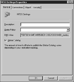
  5. Right-click NTDS Settings, and select Properties.
  1. Select or clear the Global Catalog Server checkbox, which the Screen shows.
  1. Click Apply, OK.
You must allow for the GC to replicate itself throughout the forest. This process might take anywhere between 10-15 minutes to even several days, all depending on your AD infrastructure.


Active Directory Partitions

The Active Directory database is logically separated into directory partitions:
  • Schema partition
  • Configuration partition
  • Domain partition
  • Application partition
Each partition is a unit of replication, and each partition has its own replication topology. Replication occurs between replicas of directory partition. Minimum two directory partitions are common among all domain controllers in the same forest: the schema and configuration partitions. All domain controllers which are in the same domain, in addition, share a common domain partition.

Schema Partition

Only one schema partition exists per forest. The schema partition is stored on all domain controllers in a forest. The schema partition contains definitions of all objects and attributes that you can create in the directory, and the rules for creating and manipulating them. Schema information is replicated to all domain controllers in the attribute definitions. Directory Partitions

Configuration Partition

There is only one configuration partition per forest. Second on all domain controllers in a forest, the configuration partition contains information about the forest-wide active directory structure including what domains and sites exist, which domain controllers exist in each forest, and which services are available. Configuration information is replicated to all domain controllers in a forest.

Domain Partition

Many domain partitions can exist per forest. Domain partitions are stored on each domain controller in a given domain. A domain partition contains information about users, groups, computers and organizational units. The domain partition is replicated to all domain controllers of that domain. All objects in every domain partition in a forest are stored in the global catalog with only a subset of their attribute values.

Application Partition

Application partitions store information about application in Active Directory. Each application determines how it stores, categorizes, and uses application specific information. To prevent unnecessary replication to specific application partitions, you can designate which domain controllers in a forest host specific application partitions. Unlike a domain partitions, an application partition cannot store security principal objects, such as user accounts. In addition, the data in an application partition is not stored in the global catalog.
As an example of application partition, if you use a Domain Name System (DNS) that is integrated with Active Directory you have two application partitions for DNS zones — ForestDNSZones and DomainDNSZones:
  • ForestDNSZones is part of a forest. All domain controllers and DNS servers in a forest receive a replica of this partition. A forest-wide application partition stores the forest zone data.
  • DomainDNSZones is unique for each domain. All domain controllers that are DNS servers in that domain receive a replica of this partition. The application partitions store the domain DNS zone in the DomainDNSZones.
Each domain has a DomainDNSZones partition, but there is only one ForestDNSZones partition. No DNS data is replicated to the global catalog server.

Installing & Configuring SharePoint Server 2007-Step-by-Step Instructions

Installing & Configuring SharePoint Server 2007

In this post, I'll demonstrate with words and screen shots how to install and get working a portal using Microsoft Office SharePoint Server 2007. Installing this product is not difficult, but it does require some forethought and planning. You can use this post as a reference for getting your version of MOSS 2007 installed.

First, you'll need Windows 2003 Server, fully patched and ready to go. I believe I've seen blog postings recently that indicate that you can install MOSS07 on a Vista server. I'll leave that discussion for other threads and posts.

Once you have the operating system ready to go, you'll want to start by running the setup.exe for MOSS 2007. Figure 1 illustrates that after you start the installation process, you'll need to enter a valid product identification key code. This key code can be found on the download site and should have been a part of what you did to get the software in the first place.

Figure 1: Product Identification Key Code Input Screen

After entering the product identification key code, click Continue. The next screen is the licensing agreement screen. Now, I always recommend that you read the licensing agreement since it is a legal document and you are bound by its' terms. But I also recognize that in the 10+ years I've been in this industry, I've never seen an agreement that I didn't agree with.............if you get my drift.

Figure 2: Licensing Agreement Screen.

Be sure to select the "I accept the terms of this agreement" check box and then click Continue.

The next screen will give you the chance to select which type of installation you wish to commit. The Basic installation is used for those who:

  • Need to install everything on a single server

  • Do not need to grow into a multi-server farm

  • Need a quick, easy deployment during installation with lead administrative effort

The Advanced option is selected by those who wish to install MOSS 2007 selecting some of the customizable features. In this illustration, we'll select the Advanced option and follow that route.

Figure 3: Installation Type Selection Screen

After clicking on the Advanced button, you'll find that the selections default to StandAlone (Figure 4). However, we'll choose Complete. The meaning of the three options is as follows:

  • Complete: Enables all of the options for one server to offer the entire range of MOSS 2007 services and features to the network. You can scale out this deployment, start and stop services on this server and use a SQL server to host your databases.

  • Web Front End: Enables only those options that allows the server to run as a web front end server. What this means is that server is merely the entry and exit point (or one of them among the other WFE servers) for the farm. The actual servers that users will consume will be hosted on other servers (presumably). This cannot be the first choice of a farm unless you plan on installing other servers in the farm to offer the services and features that users will want to consume.

  • Stand-Alone: Similar to complete, this option enables all of the services and features for the MOSS 2007 farm, but assumes that there is no SQL server, so the MSDE engine is installed locally on this server. You cannot scale out this server into a larger MOSS 2007 farm.

Note that in reality, all of the MOSS 2007 binaries are installed in all three choices. All these choices really do is (pragmatically, not technically) turn on and off the code that is required for the server to fulfill the functions that have been assigned to it. Note also that you can select the location where the binaries should be installed in the File Location tab and then sign up to give feedback directly to Microsoft if you'd like to do this.

Make your selections, then click Install Now.

Figure 4: Server Type Selection Screen

During the installation, you'll be presented with a status bar that is illustrated in Figure 5.

Figure 5: Installation Status Screen

After installation has completed, you'll be given the chance to run through the SharePoint Products and Technologies Configuration Wizard (Figure 6). You'll use this wizard to commit the initial configuration options for your new SharePoint farm.

Figure 6: Entry screen to the SPPT Configuration Wizard. Note that you can come back to this screen using the Administration menus that automatically install with the SharePoint Server binaries

One you start the SPPT wizard, you'll receive a pop-up box (Figure 7) that will inform you that certain services are going to be stopped. Be sure it is a good time to stop these services before moving on with the configuration options for your farm.

Figure 7: Informational Pop-Up Box

The following set of screens in the SPPT Configuration Wizard are design to help you setup the farm. In Figure 8, you'll be able to create a new farm or join and existing farm. Farm membership, at the server level, is determined by which servers are using the same configuration database in SQL and which servers are not. In my illustration, I want to create a new farm, so I select the "No, I want to create a new server farm" radio button. If I had wanted to connect to an existing farm, I would have selected the other radio button.

Figure 8: Connect to a server farm configuration screen in the SPPT Wizard

After making our selection in Figure 8 and then clicking Next, I'm taken to the next screen illustrated in Figure 9. On this screen, I can enter the following configuration values:

  • The SQL database server name. I'm not clear if this is the host name or netbios name, but I suspect this is the host name. However, you don't need the FQDN here, but you do need name resolution to this server or SQL Instance.

  • The farm configuration database name is needed in the next input box. Note that the screen just asks for a name, but you need to understand you're entering the most persistent database name for the entire farm - the farm configuration database name. Be sure this name supports your database naming convention. You should decide the name of this database in advance of getting to this screen

  • The database access account will need to be a member of the local admins group on each SharePoint server along with having db_creator and db_security permissions in SQL. I would suggest you have an account setup just for this purpose in your Active Directory and that you have a strong password associated with this account.

Figure 9: Configuration Database Settings Screen in the SPPT Wizard

in Figure 10, you'll be asked to decide which type of security settings you want to use for your farm. First, you can specify a pre-selected port number for central administration to run on or you can allow the wizard to randomly assign a port number. As you can see, this instance of the wizard randomly selected 17386 as the port number for Central Administration (CA). If you want CA to run on a different port, then select the check box and enter the desired port number.

The issue of NTLM vs. Kerberos is one that you may at some point wish to consider. Do you want the CA application to run using NTLM (NT Lan Manager) for security authentication or Kerberos? If the latter, there are some special configurations you'll need to complete for your Active Directory (AD) before Kerberos will work. I'm finding that most administrators are happy with NTLM, though those in a larger and more secure implementations are increasingly using Kerberos. For purposes of my illustration here, I'm selecting NTLM.

Figure 10: Configure SharePoint Web Application configuration screen in SPPT Wizard

After you click Next, you'll be given a status bar that indicates how the SharePoint configuration is going. Depending on the type of server you're installing and the options you're installing, you could have as few as seven tasks or as many as eleven. Figure 11 illustrates the progress screen. Note that the caption below the status bar will inform you about the configuration actions that are being executed during this process.

Figure 11: Configuration status bar screen in the SPPT Wizard

After the configurations have been executed and committed to the SQL Server database, we finally get to CA where we can further configure our farm. We can start and stop services (Figure 12) on this server and then create web applications. In order to have portal, you'll first need to start the Office SharePoint Server Search service and then create a Shared Services Provider (SSP). I'll start the search service.

Figure 12: Services configuration screen in CA

When the search service is started, you're presented with another web page for search configuration administration that needs to be completed before the search service can start. The configuration options are pretty clear. Out of the shoot, you'll use this server for both indexing and servicing queries from users until you can get enough servers in your farm to quarantine those options in your farm. Select a location that has enough disk space for your indexes. You should plan on a space allotment of 20% relative to the amount of information you wish to index. You'll also need to input an email address, a service account and whether or not there is a dedicated WFE for all crawling activities. For now, in my illustration, since this is the first server in the farm, I'll accept the defaults and click OK.

Figure 13: Search configuration screen

After starting the search service, the next thing I need to do is create a SSP. In order to do this, I'll navigate to the Application tab in CA, click Create or Extend a Web Application, then click Create a New Web Application, then make the configurations necessary that you see in Figure 14. Most of this is pretty self-explanatory, so I won't go through each input in detail. Suffice to say that I've done two things not illustrated here. First, after creating this web application, I then web back into CA, selected the Create or Configure Core Farm Services, then selected New SSP (Figure 15) and then filled in the configuration information for the new SSP. All of the options on that page are self-explanatory, except that you must select an Index server for the SSP to operate.

Backtracking just a bit, you can't have an Index server unless the Search services is started. So, that's why I illustrated starting the search services first, then creating an SSP, then creating a portal.

Figure 14: Configuring the new web application to host the portal

Figure 15: Illustration of the SSP management interface where you can select to create a New SSP.

Once the SSP is created and the web application for the portal has been created, you can then create the portal. The way to do this is to navigate to CA and then click Create Site Collection. Be sure the http://portal is selected in the drop down list in the upper right-hand portion of the screen (Figure 16). Note that on this screen, you'll need to ensure that you are creating the site collection at the root by selecting the "Create Site at this URL" where the URL path is "root", not in the Sites managed path. Also, if you scroll down, you'll need to select the Corporate Intranet Site under the Publishing tab. Microsoft has renamed the Portal to Corporate Intranet Site and placed it under the Publishing tab for web content publishing purposes. BTW, even though I don't illustrate it here, be sure to give the site a title.

Figure 16: Create Site Collection Screen

At this point, you should now have a new portal, ready to aggregate, organize and present content for your enterprise, division or department.

SOURCE : www.mindsharpblogs.com